Измеритель параметров полупроводниковых приборов на ATmega8
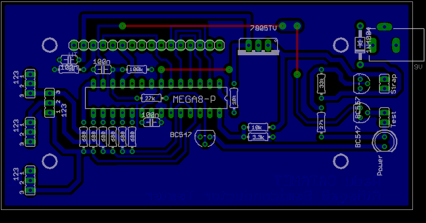
Hire is the PCB I use, but I've done some changes, I put some of SMD 100n capacitor in several places, like VCC to GND near MCU, AVCC to GND, and the 300uH coil form VCC to AVCC.

And hire is the real board measuring the SBP13007-H1 where the collector and emitter are reversed.
It seems that I forget the image ![]() sorry !!!
sorry !!!
This is the link to the picture: http://i767.photobucket.com/albums/xx316/criradu/Electronice/IMG271.jpg
I can't add the jpg, I'll try to add a zip.
I don't know way, but I can't upload any other file. This is the FW I use http://pro-radio.ru/measure/8930-71/.
MND: I don't know way, but I can't upload any other file.
Upload size is limited to 150 kb. You can use 3rd party file hosting for uploads and place link in your message.
Thanks rfc!
Dear MND,
first.
the 7805 regulator MUST have a large capacitors (no less than 4,7 - 10mkF Tantall on output, and 10-15 mkF on input), plased as close as possible to xx7805 pins. Same for MCU: 4,7- 10mkF*6V Tantall closed to power pins.
I don't see this on your PCB. This in standart connection for regulator's and MCU.
Nobody know what quality external PSU you are using... so extra large capasitor (100-220 mkF*25V )can be placed close to power jack after diode.
second.
I hope this is only mistake on picture of PCB - 6x 680 Ohm resistors instead of 3x (680 Ohm+470kOhm) ![]() .
.
MND: SBP13007-H1
Gain 800 !!!! for this transistor is impossible. Be assured ! !!!
http://doc.chipfind.ru/pdf/semiwell/sbp13007h1.pdf (650kB)
Are you sure that you don't have unexpected connection on your PCB?
I see a lot of not removed cooper between a trases.
or it's only not a good picture?
It seems that the problem was the 470k resistor. It is working PERFECT. I'm thrilled about measurements. Thanks a lot for opening my eyes. Sorry for bother you!
